
This manual covers all modules. Enable additional tabs, such as Fasteners, Felt lamination and Roof takeoff, in the Modules menu. They are hidden by default.
Sloper WEB user manual. The same manual is available from the application's Help menu. No login is needed to read it. It opens in a separate tab so you can consult it while designing.
Search using several words to find the relevant chapter. Printing includes the currently visible chapters; choose “Show all chapters” before printing the entire manual. Screenshots come from Sloper running a training project. Click an image to enlarge it. Numbers on screenshots identify interface controls; the data and quantities are for learning purposes.
No matching chapters. Try a shorter query, such as “outlet” or “PDF”.
01. Workflow
- Sign in to the company and select a user if the company has several accounts.
- Create a project. Enter the customer, EPS grades, slope, starting thickness and base insulation.
- If needed, load a PDF, DWG or image background and calibrate its scale.
- Draw a closed roof outline. Add drainage receivers, troughs, penetrations and openings.
- Click “Optimise”. Review the board layout, heights, sections and 3D view.
- Review Production, Fasteners, Felt lamination and Quotation. Complete Roof takeoff if you need quantities for the remaining roofing materials.
- Save the project and prepare documents in the Document centre. Download them to your computer.
02. Company, users and PIN
Registration creates a separate company and its administrator. The company login is an email address, and the user sets the password. A new company receives a 14-day trial. Its projects and price list are separate from other companies' data.
With a single active user who is an administrator, signing in to the company opens the application directly. After more users are added, the user selection and PIN screen appears.
- Open Settings → Users and profile.
- The administrator enters the user's name, PIN and, if appropriate, administrator permissions.
- Each employee accesses their own account using a PIN. Their work is assigned to that account.
A new company password has 8–128 characters, including at least one uppercase letter and one special character (e.g. !, @ or #). A digit is not required. Existing passwords remain valid. A PIN has 4–8 digits and may start with zero. Five incorrect PIN entries lock the selected account for 15 minutes. A legacy account without a PIN must set one before adding colleagues.
Save your work before switching users. Changing the account also affects the login session in other browser tabs. “Sign out” is in the top menu bar.
03. Projects, saving and opening
The fixed icons on the left provide New project, Open, Save, Save as and Document centre. Hover over an icon to see its name.
- New project: the application asks whether to save your current work and starts a new project in the same window.
- Open: select a company project from the list or choose a file on your computer. Use search to find a name.
- Save: updates the current project on the server.
- Save as: creates a separate project version; use it for customer alternatives.
- .rsp.json copy: the downloaded file lets you keep your own copy outside the server.
A project being edited in another session may be read-only. Once that session closes, use Refresh access. You can also use “Save as” to work on a separate copy. Recovery copies help restore work but do not replace deliberate saving.
The server stores projects without the drawing background. After ending a session and reopening the project, load the background again. PDF, DXF and HTML documents are temporary downloads, not a company archive.
04. Design workspace and selection
Start with the three areas of the screen. Choose an action on the left, work on the drawing in the centre, and read or change the selected element's data on the right.
Step-by-step instructions
- Open the Project tab. The top tabs switch modules; they do not create a new project.
- Hover over an icon on the left and wait for its name. Click to activate the tool.
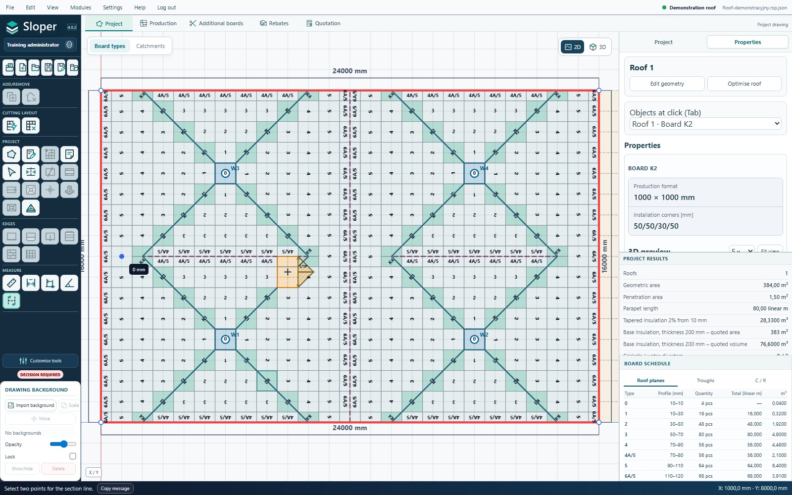
- Click a roof. Check the Properties panel on the right to see what is selected. Clicking a board opens that board's data.
- For overlapping elements, use “Elements at the click position (Tab)”. Select the object by name instead of trying to hit an obscured line.
- Use the mouse wheel to zoom; hold the wheel button to pan. Esc exits the active tool.
Expected result: When a roof is selected, results and the board list refer to that roof. With no selection, they cover the entire project.
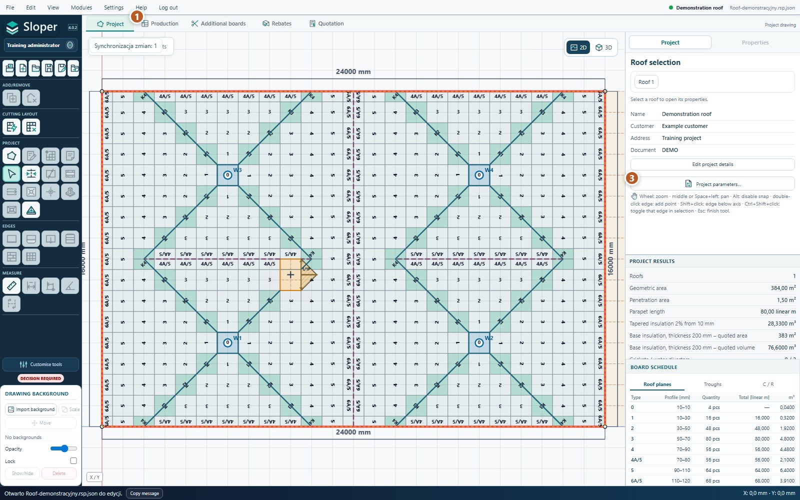 Enlarge screenshot ↗
05. PDF, DWG and image backgrounds
- Choose “Load background” and select a PDF, DWG or image file.
- For a multi-page PDF, select the required page.
- Start scale calibration, mark two points with a known distance and enter the actual dimension in mm.
- Set position, rotation and transparency. Lock the background if moving it interferes with drawing.
The visible PDF area sharpens after zooming stops. A scan cannot become clearer than its original. DWG loads directly as a model-space background without manual conversion; it is not a CAD layer editor. Unsupported objects or missing references may limit the displayed content.
When changing the scale, the application may ask whether to scale associated roofs. Choose carefully: this changes project geometry, not just the background appearance.
06. Outline and geometry editing
Exercise: draw a rectangular roof. Close the outline before adding drainage and calculating the roof surfaces.
Step-by-step instructions
- In the Project tab, select the “Roof outline” icon on the left.
- Click the first corner, move the cursor and mark the next corners. The segment preview and snapping help maintain the direction.
- To finish the roof, click the first point again. Pressing Esc alone does not close the polygon.
- Click inside the roof and name it in Properties. Select edges and assign their functions, such as parapet or gutter.
- To correct geometry, select the roof and choose “Edit geometry”. Move corners or edges and enter exact dimensions in Properties.
- After changing a completed roof, run optimisation again.
Expected result: The closed roof appears in the list on the right. There is no board schedule until optimisation has been performed.
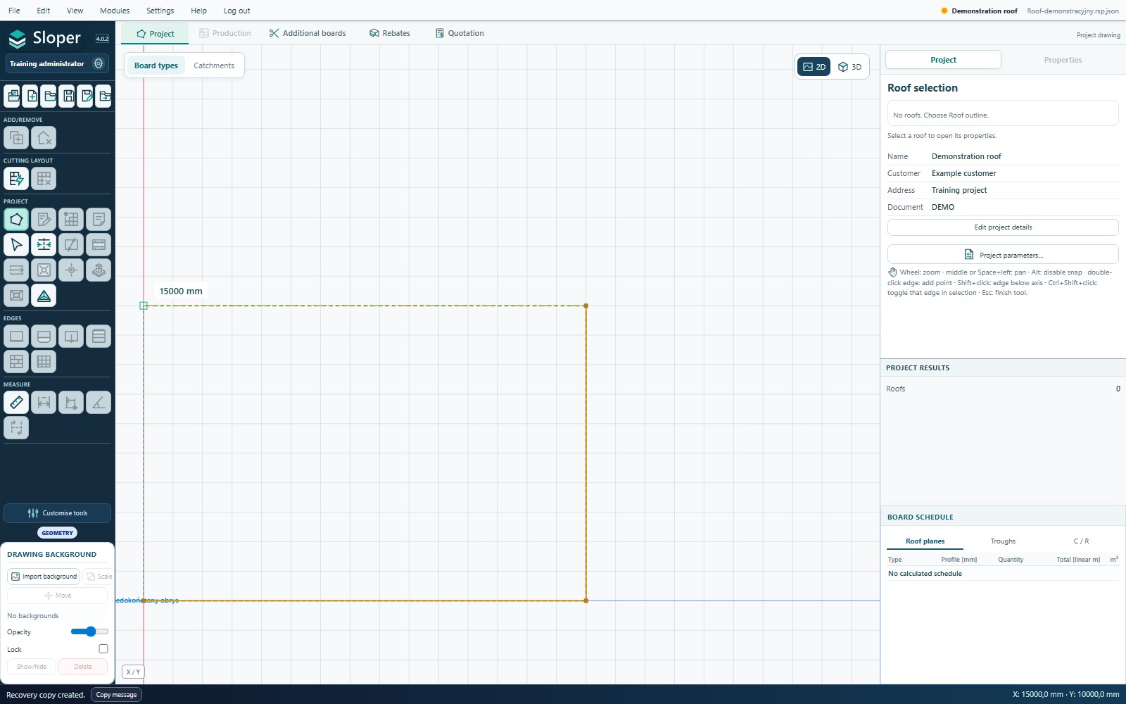 Enlarge screenshot ↗
Reading the result and avoiding confusion
- Esc pauses the sketch. To continue, return to Roof outline and select an end point of the sketch.
- Lock only dimensions that must remain unchanged. Conflicting constraints may prevent a length change.
- Ctrl+C / Ctrl+V copies the entire selected trough, penetration or opening, even when its edge is selected. A trough is copied together with its axis.
07. Project and individual roof parameters
Project parameters are the starting point. Each roof can also have its own slope, material and base insulation settings.
Step-by-step instructions
- Click “Project parameters…” on the right without opening Production.
- Select EPS grades, starting thickness of tapered insulation, slope percentage and base insulation parameters. Cricket parameters are in the same form.
- Check the units beside each field: thicknesses and widths are in mm; slope is in %.
- Confirm the form. To change just one roof, select it and use “Change this roof's parameters”.
- For a roof without base insulation, select tapered insulation only or disable the base layer in that roof's parameters. Do not change the common settings of all roofs by mistake.
Expected result: Check the roof status after changing parameters. If its layout is out of date, click Optimise before comparing quantities and prices.
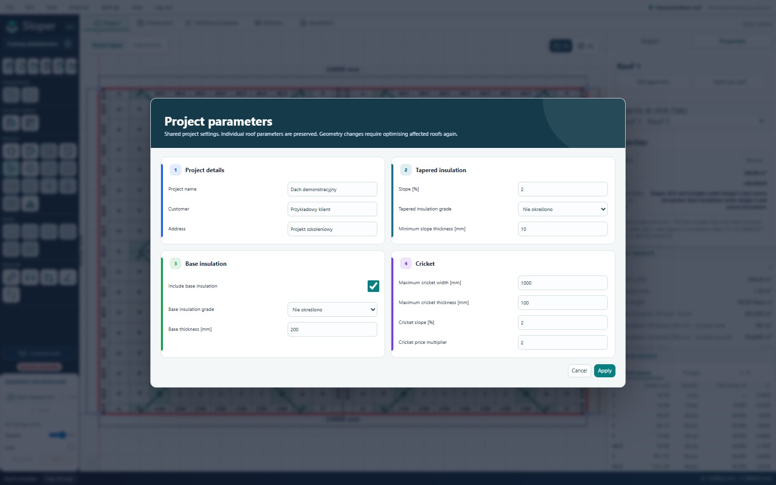 Enlarge screenshot ↗
08. Edge functions
An edge can represent a parapet, wall, gutter or linear drain. Its status affects drainage, visualisation and takeoff. The outline alone does not define these functions.
Select an edge and assign its status using a tool on the left or Properties. Ctrl+click selects several edges of the same roof so you can change them together.
Takeoff marks unassigned edges with a dashed line and highlights the current edge in a bright colour. Previous and Next guide you through the list. “All edges” applies to unassigned segments and preserves existing assignments.
09. Outlets with and without board 0
Placing an outlet and setting the board direction are separate actions. After clicking the outlet centre, read the prompt beside the cursor.
Step-by-step instructions
- Select the roof that the outlet will belong to.
- Choose the outlet with board 0 icon or the adjacent outlet without board 0 icon.
- Click the outlet position on the roof. For an internal outlet, the prompt says “Select an edge to orient the outlet”.
- Hover over the appropriate roof edge. When it turns yellow, click it to set the board orientation.
- After adding all drainage receivers, click Optimise. Review the layout around every outlet.
Expected result: The outlet has a position and orientation. Properties shows edge distances and lets you change its placement.
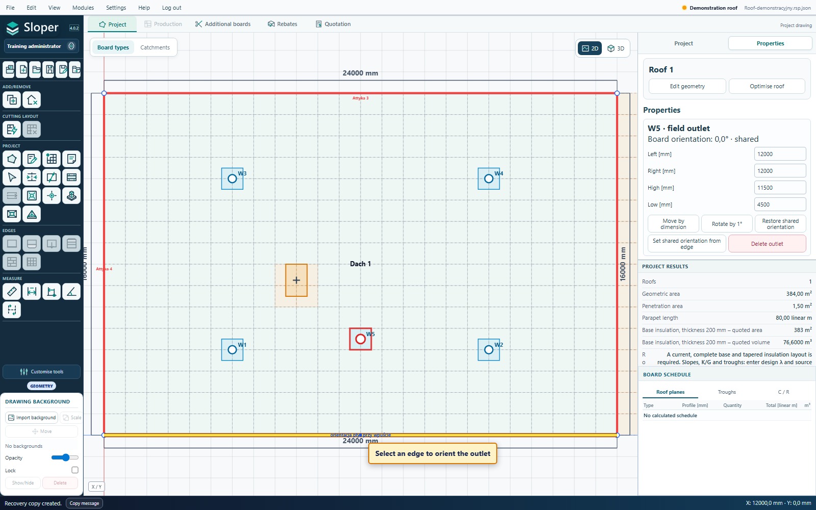 Enlarge screenshot ↗
Reading the result and avoiding confusion
- Snapping detects an edge or corner placement. The edge then defines the orientation without another click.
- An outlet with board 0 placed at a straight edge has its centre offset by 500 mm. At a rectangular corner, this applies to both edges. An outlet without board 0 stays on the selected edge or corner.
- Without board 0, the layout starts at the outlet centre. Trimming an outlet board at an obstacle is an installation operation; production counts a full board.
10. Troughs and their drainage axes
Add the trough and its drainage axis separately. The trough axis is a short TRANSVERSE segment, not a line along the trough.
Step-by-step instructions
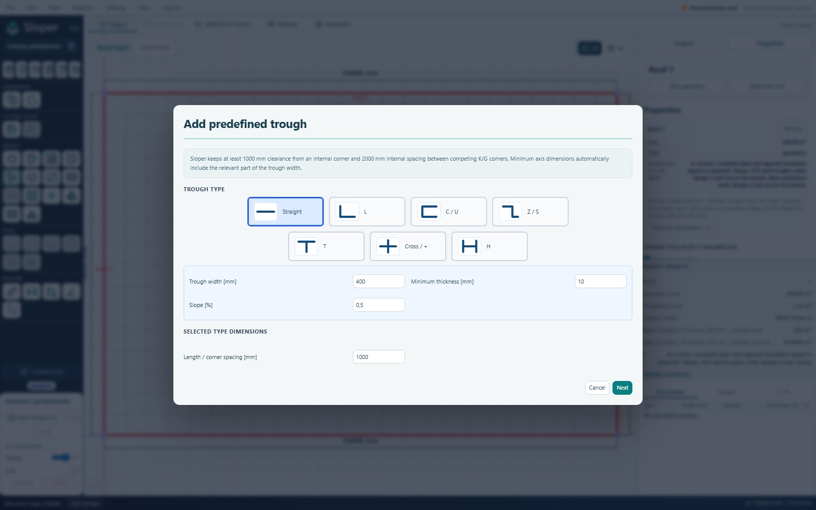
- Select a roof and activate Add trough. Choose a shape in the form.
- Enter width, arm lengths, starting thickness and slope. Click Next and place the trough on the drawing.
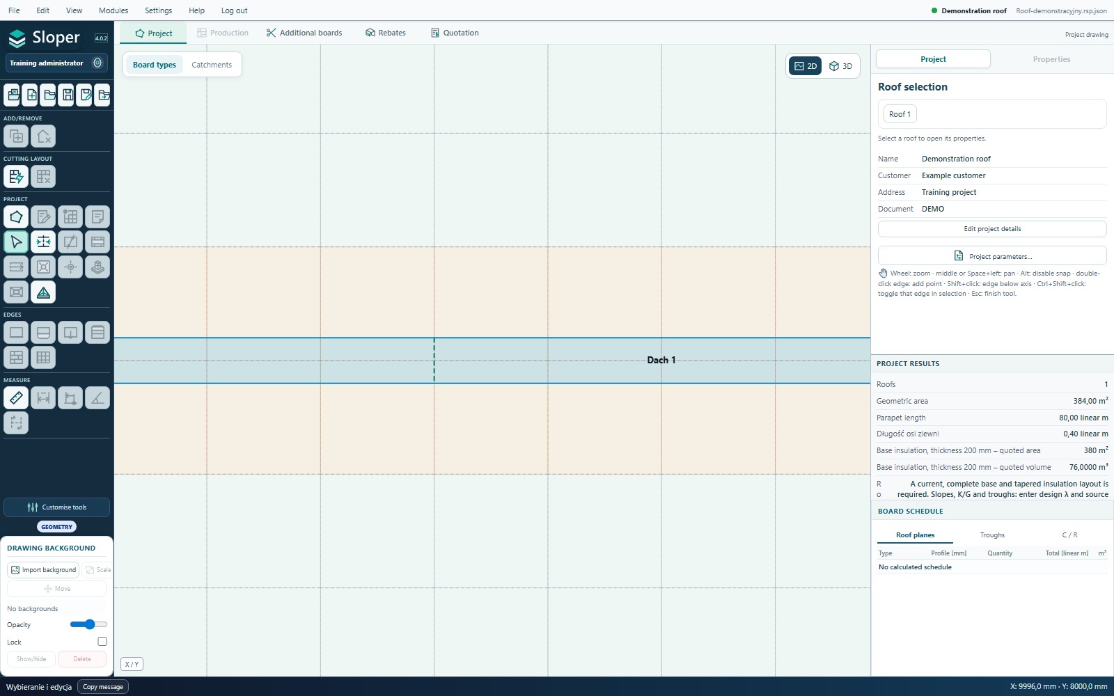
- Select the inserted trough. The drainage axis button reminds you that the axis is missing; it is unavailable unless the appropriate trough is selected.
- Choose “Trough drainage axis”. Mark two points on opposite sides across its width, perpendicular to the long edge.
- If the project includes base insulation, answer the question about insulation under the trough. This is a separate choice from the base insulation of the main roof surface.
- Click Optimise and check the trough in the layout and section.
Expected result: The trough has its own assigned axis. To change the axis position, select it, delete it and draw it again; do not drag it.
 Enlarge screenshot ↗
 Enlarge screenshot ↗
Reading the result and avoiding confusion
- A trough may extend beyond the roof or overlap a chimney or opening. The installation layout covers the available roof area.
- Base insulation under a trough is rounded down to whole centimetres: 193 mm becomes 190 mm. A roof designed without base insulation does not require this question.
- Trough board width follows the trough width; A/B and quantity allowances do not increase it. R rotates the trough by 45°.
11. Drainage axes and receivers outside the roof
Roof drainage axes and trough drainage axes are different tools. First select the roof to which the axis should belong. A roof axis may lie outside the outline: it then represents a virtual outlet controlling the slope layout.
Optimise after adding an axis. Select it anywhere along its length, including outside the roof, and delete it without deleting the outline. If an axis, edge and cricket overlap, use the object selector.
Valleys and ridges show the calculated roof division. They are not manually added outlets. Division is calculated during optimisation, not after every cursor movement.
12. Penetrations, openings and nested roofs
A roof penetration represents an obstacle, such as a chimney. An opening is an area without roof covering or a surface in the 3D model. A roof within a roof is a separate raised part. Choose the correct type rather than substituting a visually similar one.
Penetrations can also have L/T outlines. The 3D model preserves their shape, wall insulation and cap. Check dimensions and insulation in Properties or the building parameters.
The layout accounts for trimming around obstacles. Where possible, smaller A/B boards are selected. A whole board is removed from the count only if it is unnecessary on the remaining roof area. Check the result after reshaping or moving an opening.
13. Crickets and water diversion
Add a manual cricket on a roof or as a standalone item. For free drawing, the form opens after you indicate both ends and the installation side.
Step-by-step instructions
- Select the cricket tool. Select the roof first if the cricket should belong to it.
- Click the low point, then the high point of the segment. Snapping works at both clicks.
- Move the cursor to the side where the cricket should lie and click a third time.
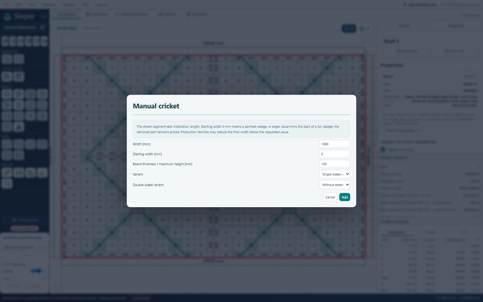
- Enter board width and thickness in the form. Choose a single-sided or double-sided variant.
- For a double-sided cricket, choose “Without extensions — classic method” or “With extensions — production optimisation”.
- Leave starting width at 0 mm for a pointed start. A larger value trims the start of a larger nominal wedge.
- Click Add. If a layout already exists, Sloper recalculates the roof; wait for the result.
Expected result: Check actual length, side and width on the drawing. Select and delete an automatic cricket at a penetration if you want to replace it with a manual solution.
 Enlarge screenshot ↗
Reading the result and avoiding confusion
- The trimmed-off start remains part of the nominal cricket included in production and pricing. Installation and production lengths may therefore differ.
- At two adjoining walls, crickets extend past the corner and are trimmed along its bisector. The installation document shows the set together with the obstacle.
- Production groups left- and right-handed wedges by nominal length before trimming. Extension boards are included in the relevant standard cutting layouts.
14. Optimisation and result review
Optimise calculates roof planes, divisions and boards for the drawn outlets. The progress window shows the actual processing stage. The number of variants examined is neither a count of finished roofs nor a completion percentage.
Cancel is available in the progress window during interruptible stages. Some final operations must finish. After cancelling, check the layout status before production.
- Check that all roofs have a valid status and the correct layers selected.
- Review corners, outlets, troughs, valleys, ridges and trimming around openings.
- Use sections and 3D to assess heights.
- Check cutting-layout completeness in Production. Missing pieces must not be treated as a complete roof quotation.
A network interruption should not require clicking Optimise again. Wait for result reception to resume. If the server process is lost, recovery from an emergency copy may be necessary.
15. Standard, A/B and K/G boards
A selected board and its production counterpart do not always have the same outline: the roof displays the item after installation trimming.
Step-by-step instructions
- Choose the selection tool and click the roof.
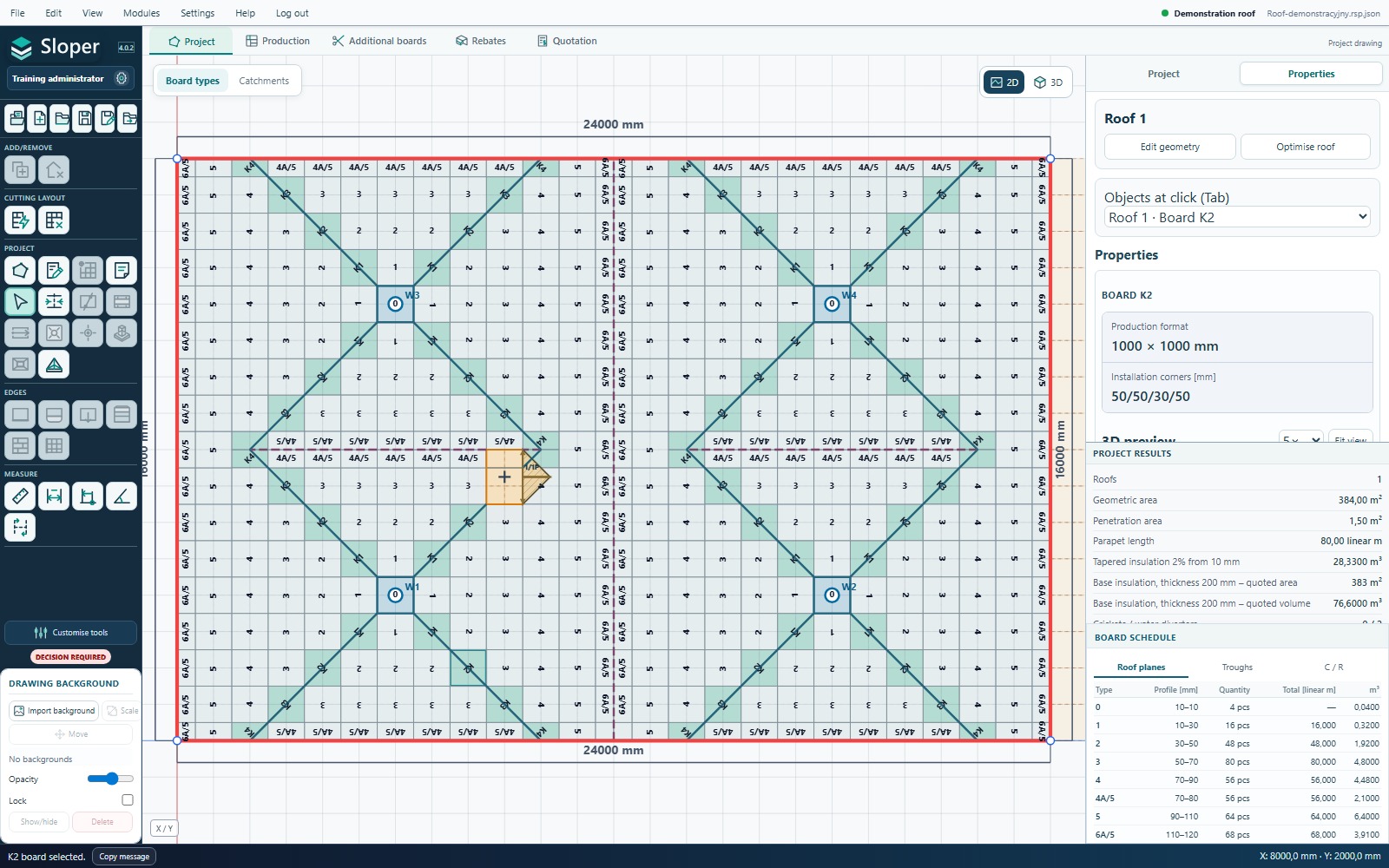
- Click the required board. If several objects overlap, select it from the list in Properties.
- Read the production format and installation corner heights in mm. 50/50/30/50 means four heights, not side lengths.
- Scroll Properties to the 3D preview. Default 5× exaggeration makes the slope visible; numerical values remain actual dimensions.
- Compare the item with the list on the right. A row for one profile may combine full boards with the final partial metre.
Expected result: For example, ten full profile-1 boards and one 0.8 m-wide board appear as 11 pieces and 10.8 linear metres in one row.
 Enlarge screenshot ↗
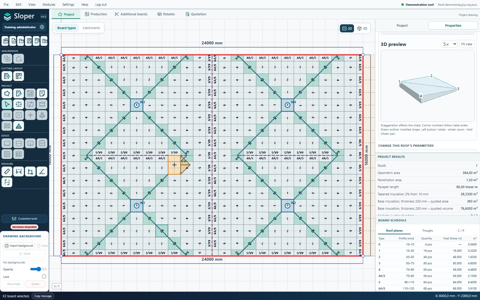 Enlarge screenshot ↗
Reading the result and avoiding confusion
- 1, 2, 3… denote standard profiles. A partial transverse metre does not change the name.
- A/1–A/5 are downslope size classes of 100, 200, 250, 333 and 500 mm. The digit after the slash is a class number, not a dimension in mm.
- B continues profile A. K/G boards form changes between roof planes; 0 is the outlet board.
- The mineral palette distinguishes standard/A/B boards, mint K, steel-blue G and amber crickets. Catchments switches to outlet areas instead.
16. Allowances
New projects start without additional allowances. Normal rounding to an A/B class is not a manual allowance. All allowance fields accept mm.
- Add A/B allowance: adds the entered value to the downslope dimension and selects the appropriate production class.
- Add quantity allowance: increases a profile's total length; for example, 100 mm changes 12.4 to 12.5 linear metres.
- Add global allowances: sets the same value in both directions.
- Remove allowances: also removes individual overrides.
Set an individual allowance in a profile row. Confirming the same value again does not add it twice. Individual values override global ones. Troughs keep their exact width without these allowances.
The volume-increase panel shows the extra material compared with the same layout without allowances. It does not compare full-block counts.
17. Production and cutting layouts
Production answers two different questions: how many blocks to prepare and how much material is included in the price. Check the scope first, then quantities, then each cutting-layout card.
Step-by-step instructions
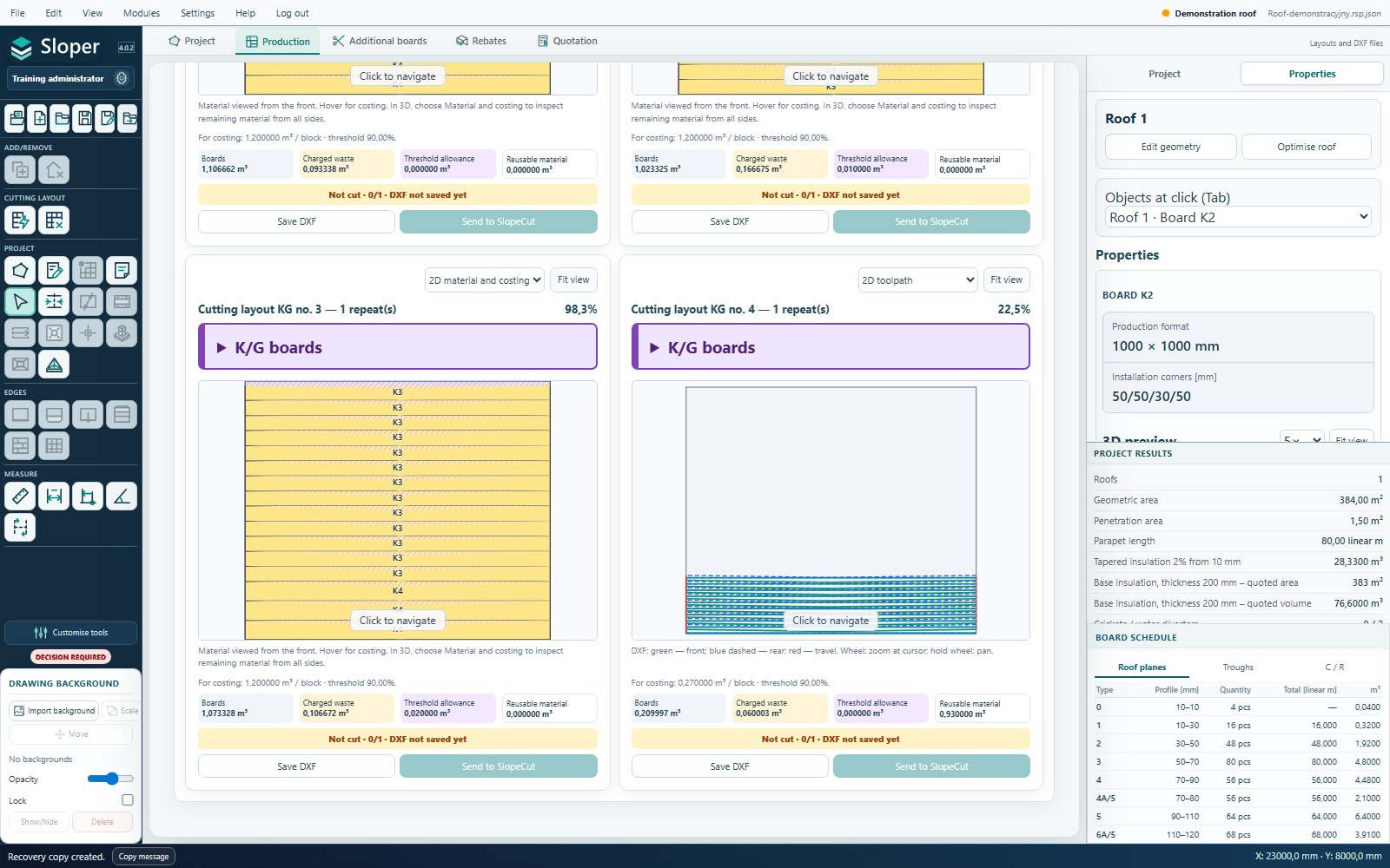
- Open Production. Under “Scope of this production stage”, choose the entire drawing or specific roofs. The thumbnail shows the calculation scope.
- Read the four top panels. Full-block count is the material to prepare in production; board volume is the sum of solids to be cut.
- Below, compare four costing-volume columns: standard and linear-metre boards, troughs, K/G and crickets. Each uses its own rate.
- Expand “Calculation details” for a group. For each B/K/G layout, read repetitions, used portion, threshold and priced quantity.
- Scroll to the block cards. Read the number and sets/repetitions. Identical layouts are grouped; one card can represent several cuts.
- Expand the coloured cutting-type heading and check block orientation. Use the selector at the card's top right for material and costing, 2D overview, toolpath or 3D.
- Click the preview to enable navigation: wheel to zoom, hold the wheel to pan. Fit restores the whole block. Outside an active preview, the wheel scrolls the module.
- Only after checking, save the DXF or send the layout to the connected SlopeCut.
Expected result: This example needs 25 blocks totalling 30.0000 m³. The boards themselves occupy 27.7947 m³. Pricing uses 24.46 m³ for standard tapered boards, 3.87 m³ for K/G, 0 m³ for troughs, and a separate 0.10 m³ for crickets. These quantities mean different things and must not be equated.
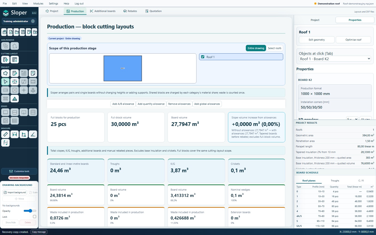 Enlarge screenshot ↗
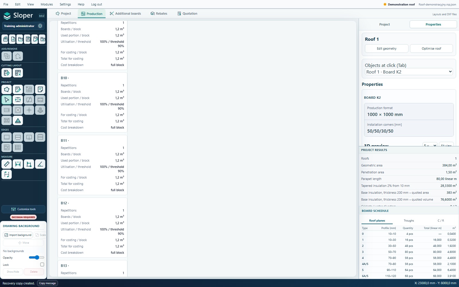 Enlarge screenshot ↗
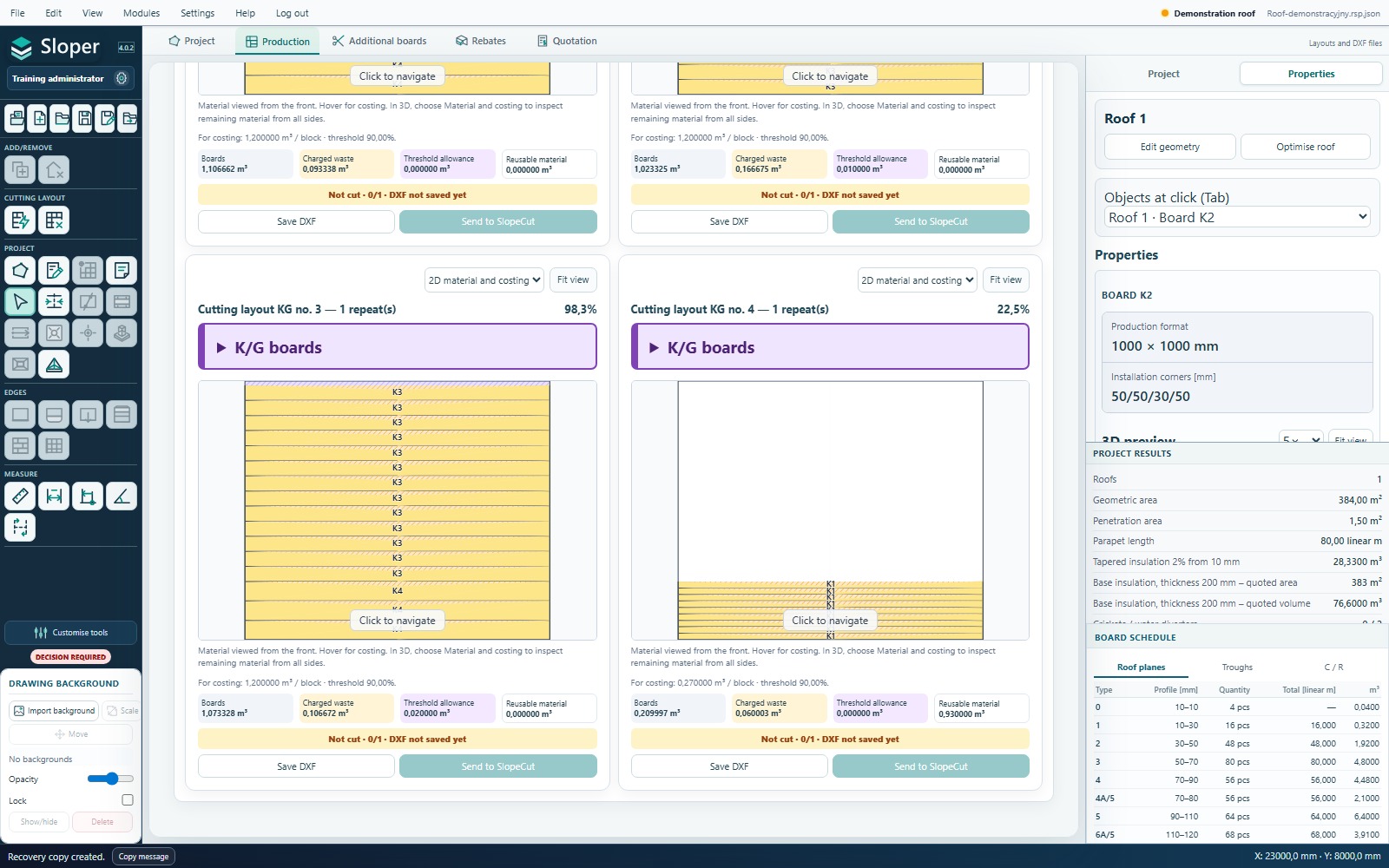 Enlarge screenshot ↗
 Enlarge screenshot ↗
Reading the result and avoiding confusion
- Board volume includes pieces to cut: tapered boards, K/G, troughs, Additional boards and manual rebates. It excludes ordinary base insulation and crickets.
- “Waste included in production” is used material not recovered as boards. “Threshold allowance” is a separate component of full-block billing.
- The threshold concerns the occupied portion/height shown in the calculation, not just the sum of solid volumes. A 90% threshold does not mean the boards must geometrically fill 90% of the block.
- Crickets are calculated from nominal families before trimming and have no full-block threshold. Extensions cut in standard blocks are not counted twice.
- Colours and hatching in the material preview distinguish boards, charged waste, threshold allowance and uncharged stock. Do not confuse white stock for future use with charged waste.
- After changing a threshold or allowance, wait for automatic recalculation. If missing pieces or incomplete layouts are reported, the result is not complete roof production.
18. DXF and SlopeCut
Save a single DXF from a block card; Document centre prepares production document sets. The toolpath preview lets you check move order without another program.
“Send to SlopeCut” becomes available for a ready layout only after a connection to local SlopeCut is confirmed. Installation alone is insufficient: start a connector-enabled version and pair the workstation.
- In Sloper, open Settings → SlopeCut connection and copy the pairing data.
- In SlopeCut on the operator's computer, choose “Connect to Sloper WEB”, paste the data and click Connect. The single-use code expires after 5 minutes.
- Once connected, choose “Send to SlopeCut” on the layout. It opens on the operator's workstation.
Sending a layout does not start cutter motion. The operator checks it and starts cutting in SlopeCut. Completion confirmations and reversed cut markings return to Sloper Production. After a connection interruption, confirmations not yet saved on the server are sent when the same workstation reconnects.
The connection lasts up to 8 hours. Closing SlopeCut or losing the connection disables sending again. Repeat pairing if needed; disconnecting is also available in the connection window. Do not share pairing codes.
DXF download remains available for ready layouts and does not mark a block as cut. Without the connector, open the downloaded file in SlopeCut at the cutter workstation.
19. Supplementary cuts and rebates
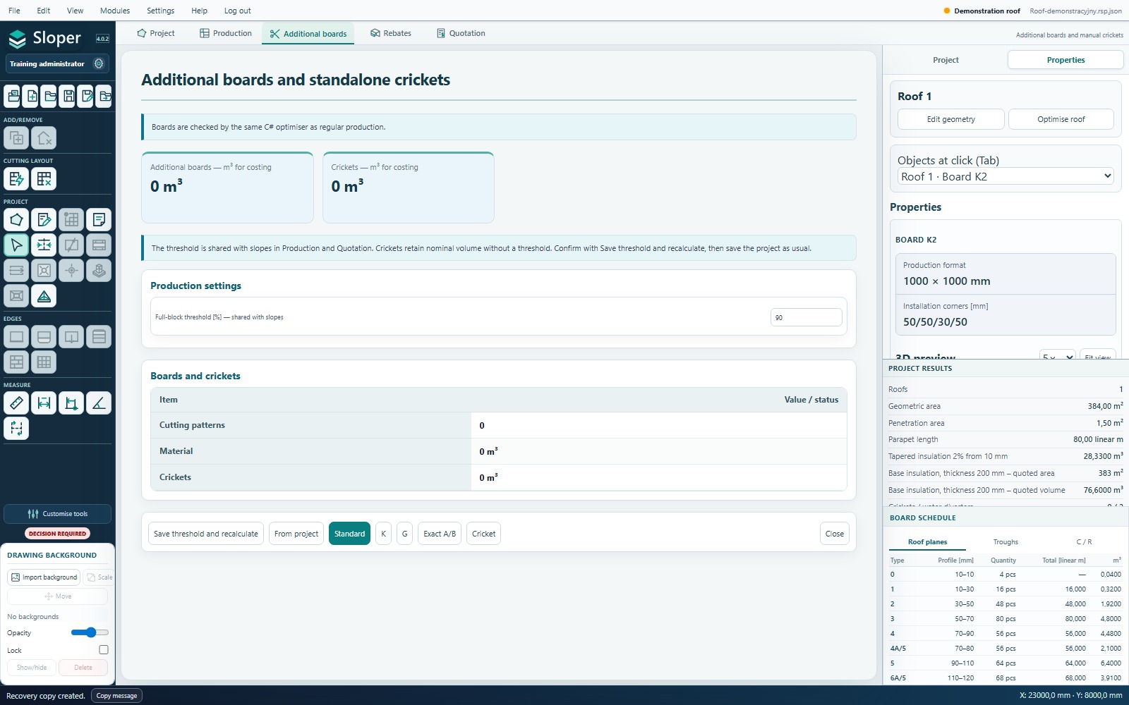
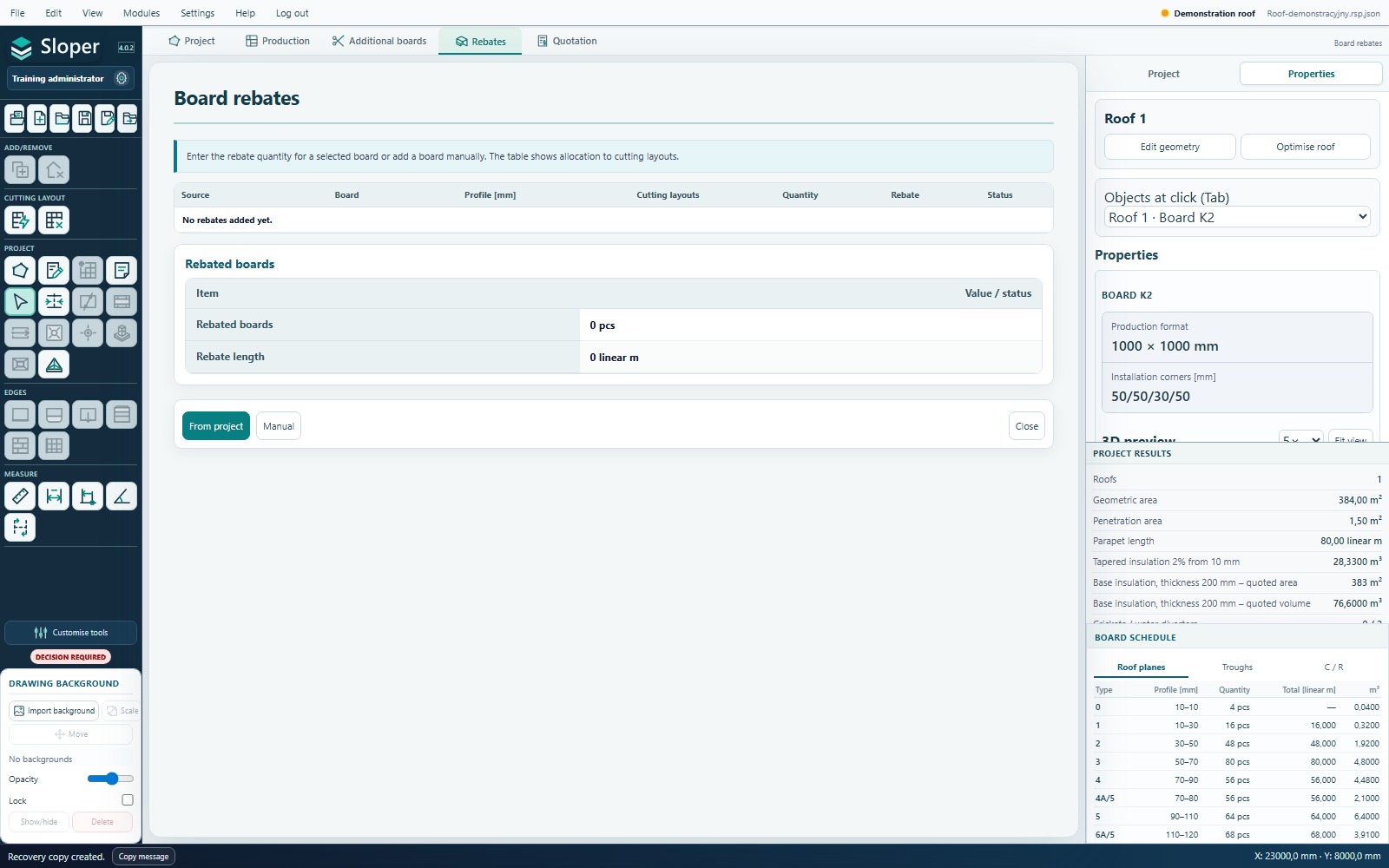
Additional boards are for supplementary board orders. Rebates specify machining of selected pieces. These are separate tabs.
Step-by-step instructions
- In Additional boards, add a profile and specify quantity, dimensions, low and high thickness. For K/G, the selected type determines the corner arrangement.
- Confirm the item and check the list. Prepare cutting layouts and a separate additional-board quotation; the original roof offer remains separate.
- In Rebates, select a project board and quantity to machine, or add a board manually.
- For an OSB rebate, enter width and depth; for a wedge cut, enter its cutting parameters. Confirm and check the accepted-piece table.
- Return to Production and inspect the toolpath. Sloper allocates rebated pieces to suitable blocks.
Expected result: Request, for example, ten rebates in profile 5, not “piece 15 in block B7”. Rebated pieces use full pieces in the standard cutting process; remaining pieces can be cut to linear-metre lengths.
 Enlarge screenshot ↗
 Enlarge screenshot ↗
20. Sleeve and screw selection
The default scope is all roofs, with Guardian ASTL and concrete screws as the default system. The drawing should show the same scope as the quantities. Apply system changes to the selected scope.
Sloper chooses the longest suitable sleeve, then the shortest suitable screw in the available catalogue. Length depends on actual thickness at the point, including base insulation and specified extra layers. Coloured bands group identical sets; small dots mark positions.
If ŁINO concrete fasteners lack the required length, Sloper may suggest suitable ASTL sets. Approval does not replace substrate and catalogue compatibility. Red empty points indicate unassigned fasteners.
The assumption of four fasteners/m² serves this quantity model. It is not a wind-uplift or fastening-capacity calculation. Check requirements for the actual roof and substrate.
21. Bitumen felt lamination
Checkboxes separately select membrane lamination for tapered boards, base insulation, troughs and crickets. Choose standard or thicker laminate for each group. Omitting existing troughs or crickets may require confirmation.
Lamination prices and rebate surcharges are in the price list. Quotations receive separate lamination items. Troughs and crickets use 1 linear metre × 1.5 m²; billed length follows nominal production, including the start before trimming.
Selecting lamination does not remove the insulation price. Review the quotation and covering variant in the material takeoff.
22. Quotation and price list
Quotation uses calculated products and rates. It is not a cost estimate for all roofing work. Complete roof and production layouts are required first.
Step-by-step instructions
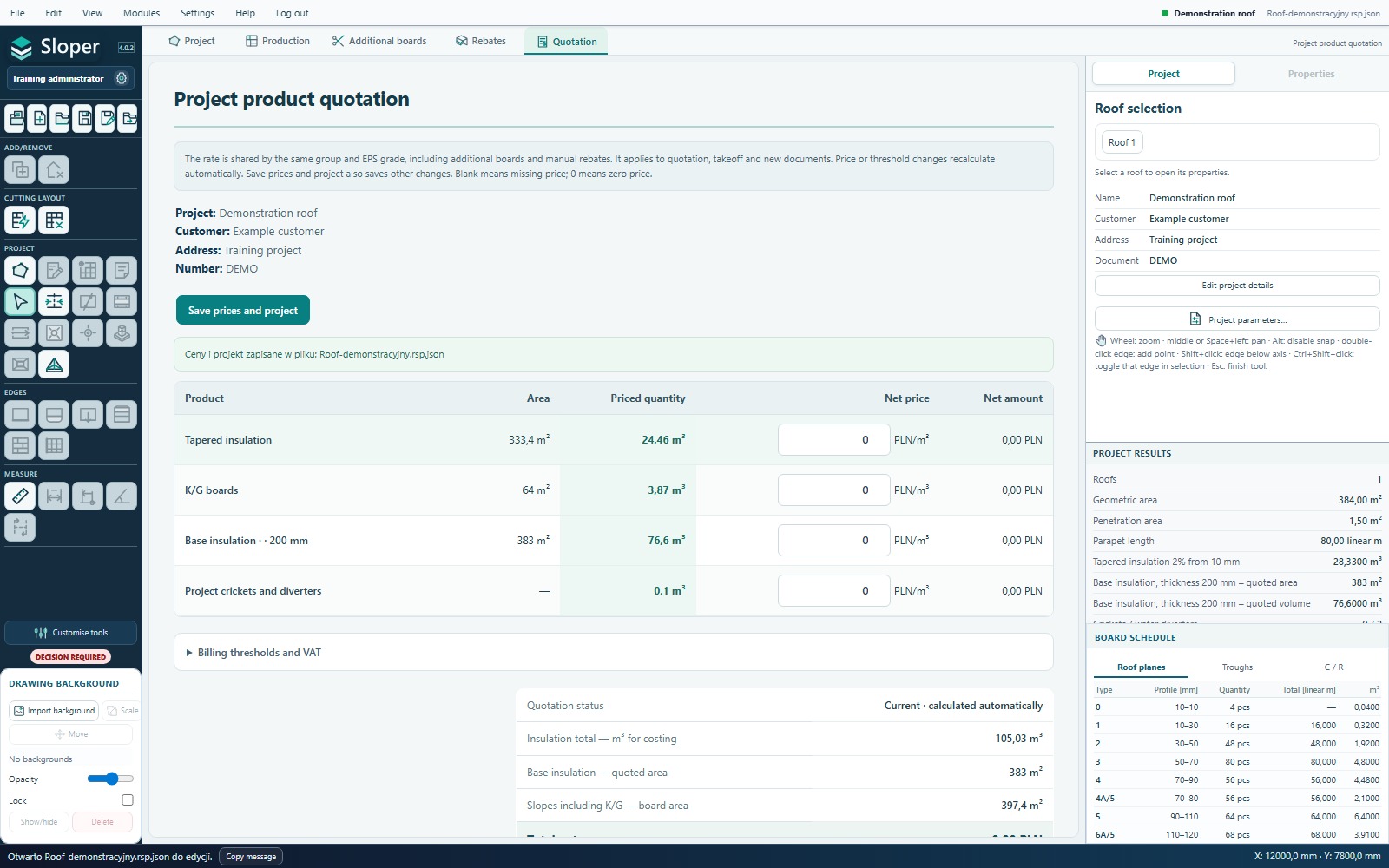
- Open Quotation. Check EPS grade, unit, quantity and rate for each group.
- Change the price in its field and wait for automatic recalculation. A project rate is shared by the same group and EPS grade in related calculations.
- Compare m³ with the corresponding Production column. Do not substitute the geometric board volume.
- Use “Save prices and project” to preserve changes. Previously generated documents do not update themselves.
- Generate a new quotation PDF in Document centre. The customer receives tapered insulation and crickets as sets; base insulation under troughs is described separately.
Expected result: A price change recalculates the project but does not change a downloaded PDF. Generate a new document after every significant change.
 Enlarge screenshot ↗
Reading the result and avoiding confusion
- A grade priced at 0 is inactive in the company price list. Before confirmation, complete required services and at least one grade with a positive price.
- A missing U-value means required thermal data must be completed; it does not mean U equals zero.
- The screenshot shows a training project. Displayed amounts are neither a commercial offer nor recommended rates.
23. Roof material takeoff
- Classify all required edges. Sloper guides you through unclassified segments and supports group assignment.
- After classifying the edges, proceed to the questionnaire.
- Enter shared roof parameters or split the takeoff by roof.
- Specify vapour control, fixing/bonding of layers, roof covering, parapet detailing, fillets, penetrations and drainage.
- Manually enter wall height measured from the structural deck and required dimensions. For downpipes, enter count and heights; outlet count equals downpipe count.
- Review categories: insulation, membranes, sheet metal, adhesives, fasteners and gutters.
Takeoff accounts for purchasing rounding, rolls, sheets and allowances. Purchased quantity may therefore exceed geometric area. Change sheet-metal developed widths, upstands, consumption and overlaps in takeoff-rule settings.
If parameter changes require new layouts or fasteners, Sloper prepares them with a progress window. Review the approved takeoff before export, especially manual heights and material variants.
24. Dimensions, sections and comments
A section checks heights along a selected line. Draw it through the relevant outlet, trough or roof-plane junction.
Step-by-step instructions
- Return to Project and choose the section tool.
- Click the start; snapping helps you target an edge or corner.
- Click the end on the other side of the area. The drawing shows the section line and the panel shows its profile.
- Read thicknesses and layers on the profile. Move the line if it missed the required element.
- Exit the tool with Esc and return to selection.
Expected result: A section shows the finished layout along the line. It does not alter geometry or board quantities.
 Enlarge screenshot ↗
Reading the result and avoiding confusion
- Automatic dimensions describe roof edges. Use separate tools for extra dimensions and annotations.
- Customer comments also do not change calculations. After importing them, the designer implements agreed changes.
25. 3D view and walkthrough
The drawing-area corner switch changes 2D to 3D using the current layout. Slopes are exaggerated 5× and shaded by height by default. Choose 1× or 10× if needed; an on-screen notice identifies the scale.
Rotation shows simplified outlines; releasing restores the full model. Hold the wheel to pan. Layers show base insulation, slopes, crickets and labels. Labels lie on the board surfaces.
Surroundings are enabled by default. The building-height slider ranges from 0–20 m, starting at 6 m. Surroundings aid presentation and do not affect layouts or pricing.
Walk lets you choose a point on the roof and move with WASD or arrow keys. Hold the left button to look around; the wheel changes field of view. Esc or ending the walk restores the regular camera. This is a visualisation, not an assessment of safe access on an actual roof.
26. Thermal parameters and U-value
Sloper calculates a result at the thinnest point and another accounting for variable insulation thickness using the method identified beside the result. It does not substitute a simple average-thickness calculation.
By default, EPS base insulation, tapered boards and K/G are included. Crickets are excluded. Troughs count only when base insulation is planned beneath them. Check the grade's lambda value in the price list.
Add other construction layers in thermal parameters. The result describes the selected layers; without the structural deck and other materials it is not a full construction model. The calculation basis also appears in quotation, installation documentation and customer HTML.
27. Document centre
Document centre separates customer, installation and production materials. Select only files intended for the relevant recipient.
Step-by-step instructions
- Open Document centre using the icon on the left.
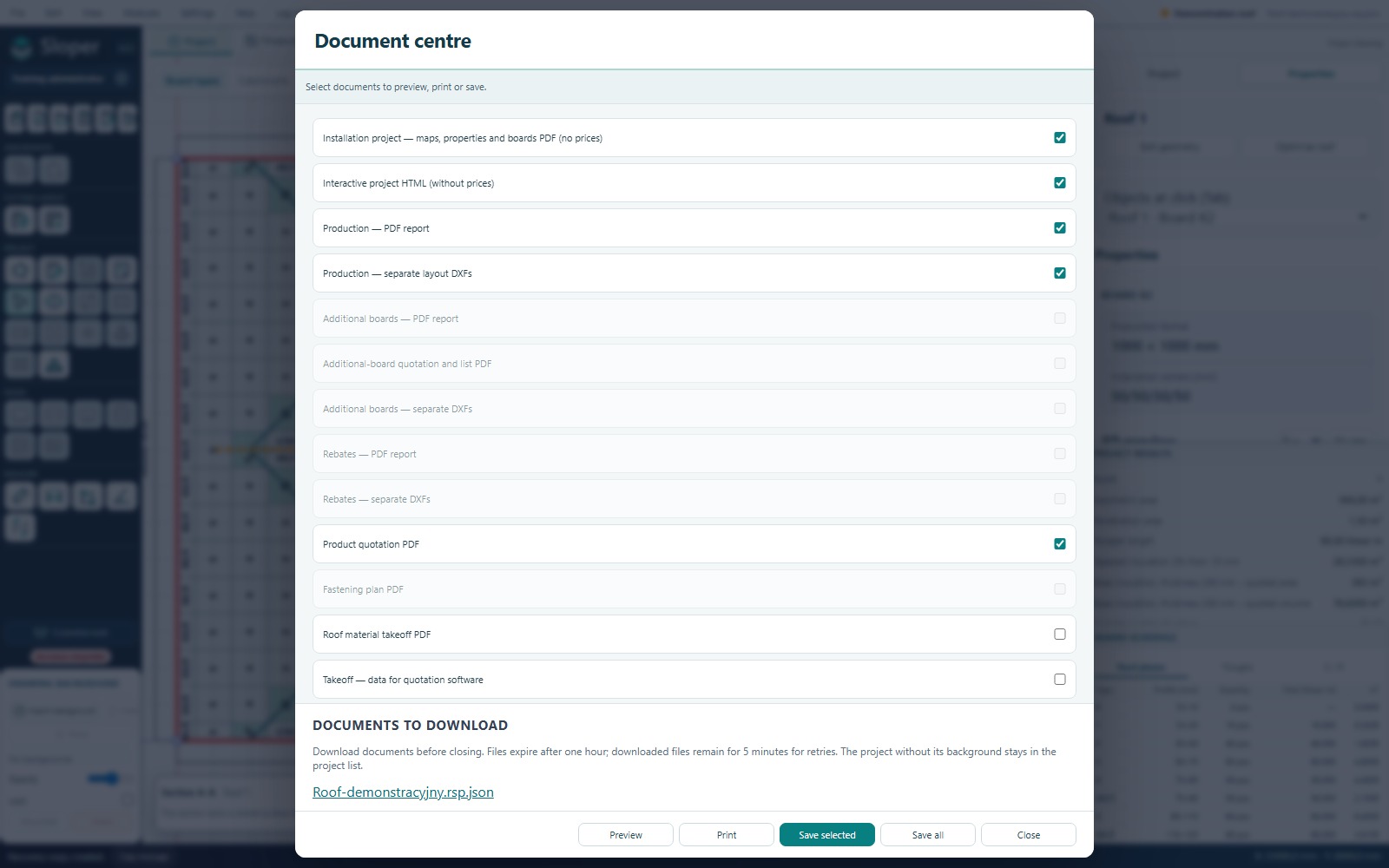
- For customers, choose Product quotation PDF and Interactive project HTML. For installers, choose the Installation project without prices.
- For production workers, choose the Production report and required DXFs. Additional boards have their own reports and quotation.
- Choose Preview, Print or Save selected. Save all prepares the complete available document set.
- Watch the progress window. Do not click again while a large file is being prepared.
- Download the finished files to your computer. Check that the correct version goes to the correct recipient.
Expected result: Installation and interactive projects do not contain offer prices. Share the quotation with designer contact details separately.
 Enlarge screenshot ↗
Reading the result and avoiding confusion
- An inactive item means module data is missing, for example no additional boards were added. It is not a save-button fault.
- The Production report contains a map, lists, block cards with repetitions and grouped crickets. Each layout card fits its preview and table on one page.
- Downloaded PDFs and HTML files are copies. Generate them again after project changes.
- Server files are temporary: undownloaded files expire after one hour; downloaded files remain for another 5 minutes for retries. Logging out removes session files.
- In the web version, download attachments and add them in your email application. The web version does not confirm automatic attachment to Thunderbird.
28. Interactive project for the customer
Share downloaded HTML with a recipient who can open it on another computer without Sloper login. It contains the finished project and viewing tools, not the server optimisation algorithm.
Selecting a roof limits properties and the board list to that roof. Selecting a board shows format, corners and 3D preview. Recipients can view sections, walks and layers, and add comments.
Print selected area lets you choose a region, then print or save it as PDF through the browser dialog. A whole-roof thumbnail shows its location. Designer contact details are omitted from this file and appear in the quotation.
HTML is a standalone copy. Server project changes require generating and sending a new file to the customer.
29. Shortcuts and troubleshooting
Open the current full shortcut list through Help → Keyboard shortcuts. Shortcuts depend on the active tool; while typing, keys belong to the text field.
| Symptom | What to check |
|---|---|
| A button is inactive | Hover to read its explanation. Check roof/trough selection, layout status, permissions and read-only mode. |
| Cannot select an axis | Choose the correct object among overlapping elements or hide the obscuring layer. |
| Background missing after opening | This is intentional in the web version: import the background again. |
| Recalculation in progress | Check the progress window. Do not repeat the operation; cancel if available. |
| Layout does not include all pieces | Read the production message and check heights, material and block settings. Do not treat a partial result as complete. |
| Document will not download | The file may have expired. Open Document centre and generate it again. |
| Connection interrupted | Wait for the reconnection message. Keep the tab open if your latest work is unsaved. |
When reporting an issue, provide the project name, action and exact message. Use the status-bar copy button to share the message. If possible, include a project copy that reproduces the issue.